
Table of Contents
This article outlines the design process, system capacity calculations, equipment selection, environmental adaptation, cost evaluation, and project acceptance procedures for solar street lighting systems on highways and urban roads. It also illustrates design approaches for different scenarios using actual projects from Sresky.
I. Why Do Highways and Urban Roads Require Different Design Approaches?
For expressways and highways, the primary design objective is to ensure visual safety under high-speed driving conditions. Key considerations include road surface luminance, lighting uniformity, glare control, and lighting performance in complex areas such as interchanges and ramps.
Urban roads, by contrast, must accommodate motor vehicles, pedestrians, cyclists, intersections, and roadside public spaces. Designers must also consider obstructions from buildings, the reuse of existing light poles, underground utility lines, and the surrounding lighting environment.
Rural roads and remote highways may place greater emphasis on grid connection costs, energy independence, and maintenance accessibility.
The main design differences between these road types are summarized below.
| Comparison Dimension | Highways / Expressways | Urban Roads |
|---|---|---|
| Lighting performance metrics | Primarily focuses on road surface luminance, overall uniformity, and longitudinal uniformity to ensure visual continuity at high driving speeds. | Balances road surface luminance or illuminance with uniformity while also considering pedestrian and cyclist visibility and vertical illuminance, where applicable. |
| Glare control | Strictly controls disability glare and other visual interference that may affect drivers. | Balances glare control and light pollution affecting drivers, pedestrians, and nearby residents. |
| Key areas | Interchanges, ramps, toll plazas, tunnel entrances and exits, and merging and diverging zones. | Intersections, pedestrian crossings, bus stops, and dedicated non-motorized vehicle lanes. |
| Lighting layout | Commonly uses bilateral symmetrical, median-mounted, or high-mast lighting, with wider pole spacing and greater mounting heights. | Often uses single-sided, staggered bilateral, or symmetrical bilateral arrangements. Coordination with trees, buildings, and utility lines is essential, and existing light poles should be reused whenever feasible. |
| Light poles and structures | Requires thorough verification of clearance, vehicle collision risks, foundations, and wind loads. Maintenance-related road closures must also be considered. | Must account for sidewalk space, underground utilities, landscape integration, and pedestrian safety. |
| Power supply reliability | Lighting failures can directly affect traffic safety, requiring longer autonomous operating periods and more robust redundancy. Hybrid solar-grid power may be appropriate. | Where grid access is available, standalone solar, hybrid solar-grid, or conventional grid-connected lighting can be selected according to the importance of each road section. |
| Maintenance requirements | Maintenance windows are limited and often require road closures. Remote monitoring, fault alerts, and long-life equipment can reduce the frequency of roadside maintenance. | Maintenance access is generally easier, but plans are still needed for panel cleaning, vegetation management, and theft and vandalism prevention. |
| Suitability for solar power | Solar lighting may be suitable for critical areas or sections where grid connection is difficult, subject to simulation and energy calculations. | Solar lighting may be suitable for new developments, areas where grid expansion is difficult, retrofit projects, and pedestrian and cycling infrastructure. |
In short, the core objectives of highway lighting are visual continuity and reliable operation, while urban road lighting must balance the needs of diverse road users with local site conditions.
Three key questions should therefore be addressed during the design phase:
- What lighting performance must the road achieve?
- Can local solar resources meet long-term operating requirements?
- Which power supply solution best meets the project’s safety, reliability, and life-cycle cost requirements?
Solar lighting solutions must prioritize road lighting performance and safety. Lighting standards should never be compromised simply to accommodate a particular product.
II. What Engineering Surveys Should Be Completed Before Design?
Before selecting equipment, the engineering team should determine the road classification, design speed, number of lanes, road cross-section, traffic volume, lighting requirements, and potential safety risks.
The following site data should also be collected.
| Survey Category | Key Data | Impact on Design |
|---|---|---|
| Road conditions | Road width, number of lanes, curves, and gradients | Lighting layout and pole locations |
| Traffic conditions | Design speed, traffic volume, and pedestrian activity | Required lighting levels and priority areas |
| Site obstructions | Buildings, trees, and bridges | PV power generation |
| Climatic conditions | Monthly solar radiation, temperature, precipitation, and wind speed | PV modules, batteries, and structural configurations |
| Operations and maintenance (O&M) conditions | Equipment accessibility, cleaning frequency, and spare parts availability | Maintenance costs and system reliability |
Particular attention should be paid to monthly solar radiation data. Average annual sunshine duration may conceal energy shortfalls during the rainy season, winter, or extended periods of overcast weather.
Lighting requirements for toll plazas, interchanges, ramps, pedestrian crossings, and other high-risk locations should be assessed individually. Not every highway section requires a continuous arrangement of standalone solar streetlights. Some projects may be better served by lighting only critical areas or adopting a hybrid solar-grid power supply.
III. Which Standards Should Solar Road Lighting Follow?
Road lighting designs should identify the applicable standards based on local regulations, road classification, traffic conditions, and client requirements. Common references include CIE 115, the EN 13201 series, and relevant IES standards and recommended practices for roadway lighting.
Projects should follow locally recognized standards and their applicable editions. Lighting levels and limits from different standards should not be combined indiscriminately.
Key design parameters include:
- Average pavement luminance or illuminance: Determines whether the overall lighting level meets the applicable requirements.
- Lighting uniformity: Controls variations in pavement brightness or illuminance to prevent noticeable visual discontinuities.
- Glare control: Reduces visual interference caused by luminaires for drivers and other road users.
- Maintenance factor: Accounts for the effects of light depreciation and surface soiling on long-term lighting performance.
- Pedestrian-area lighting: Improves visibility for pedestrians and cyclists where applicable.
Luminance and illuminance are not interchangeable. The appropriate calculation method must be selected according to road conditions, observation methods, and the applicable standards.
For expressways, the design should prioritize visual continuity under high-speed driving conditions and adequate lighting at complex interchanges. For urban roads, additional attention should be given to intersections, pedestrian crossings, bus stops, and the surrounding lighting environment.
IV. How Are Luminaire Power, Mounting Height, and Pole Spacing Determined?
Luminaire power alone does not indicate the quality of road illumination. Even when two luminaires have the same rated power, their luminous efficacy, luminous flux distribution, and photometric distribution curves may differ significantly.
Engineers should obtain authentic IES or LDT photometric files and use professional lighting simulation software to evaluate performance.
The recommended process is as follows:
- Create a road model and enter the road width, pavement parameters, and target lighting metrics.
- Determine preliminary pole locations, mounting heights, and luminaire arrangements.
- Import the luminaires’ photometric files and calculate luminance or illuminance, uniformity, and other relevant metrics.
- Adjust pole spacing, mounting heights, and luminaire tilt angles based on the simulation results.
- Verify lighting performance, glare control, and on-site construction conditions.
Common lighting layouts include single-sided, symmetrical bilateral, staggered bilateral, and median-mounted arrangements. The final design depends on the road cross-section, luminaire photometric characteristics, structural conditions, and traffic safety requirements.
For urban roads, coordination with trees, bus stops, and underground utilities is also necessary. For highways, particular attention must be paid to road clearance, pole foundations, vehicle collision risks, and maintenance safety.
Design principle: Verify lighting performance through simulation first, then optimize luminaire power and pole spacing.
V. How Is the Capacity of a Solar Street Lighting System Calculated?
The objective of system capacity design is to ensure that the photovoltaic (PV) modules can meet daily lighting energy demand and that the battery provides the required autonomous operating capability.
During the design phase, the primary calculations involve daily energy consumption, battery capacity, and PV module power.
5.1 Calculating Daily Energy Consumption
For constant-power operation:
Daily energy consumption (Wh/day) = Luminaire input power (W) × Daily operating time (h)
For example, consider a 60 W luminaire operating for 12 hours each night, with the power output reduced after the first five hours:
- First 5 hours: 60 W
- Remaining 7 hours: 30 W
Daily energy consumption is calculated as follows:
Daily energy consumption = 60 × 5 + 30 × 7 = 510 Wh/day
The actual design must also account for system losses, including those associated with the controller and battery charging and discharging.
5.2 Estimating Battery Capacity
A preliminary estimate of nominal battery energy can be calculated using the following formula:
Nominal battery energy (Wh) ≈ Daily energy consumption × Days of autonomous operation ÷ (Allowable depth of discharge × Overall system efficiency)
Assume the following parameters:
- Daily energy consumption: 510 Wh
- Required autonomous operating period: 3 days
- Allowable depth of discharge: 80%
- Overall system efficiency: 90%
The calculation is:
510 × 3 ÷ (0.8 × 0.9) ≈ 2,125 Wh
Final battery selection should also account for usable capacity, temperature effects, end-of-life degradation, and battery management system (BMS) limitations.
5.3 Estimating PV Module Power
A preliminary estimate of PV module power can be calculated as follows:
PV module power (Wp) ≈ Daily energy replenishment requirement (Wh) ÷ (Peak sun hours per day × Overall system performance coefficient)
Assume the following parameters:
- Daily energy replenishment requirement: 510 Wh
- Peak sun hours during the design month: 3.5 hours per day
- Overall system performance coefficient: 0.75
The calculation is:
510 ÷ (3.5 × 0.75) ≈ 194 Wp
These formulas are intended for preliminary planning estimates. The overall efficiency and performance coefficients should be determined based on equipment specifications, system configuration, and environmental conditions.
Final equipment selection must verify the energy balance during the least favorable month and account for prolonged rainy periods, module temperature, shading, and battery recovery capability.
VI. How Should Key Equipment Be Selected?
LED Luminaires
Evaluate actual input power, luminous flux, luminous efficacy, photometric files, ingress protection ratings, glare control, and dimming capabilities.
For highways and other high-risk areas, lighting performance and operational reliability should take priority over simply selecting higher-wattage luminaires.
Photovoltaic Modules
In addition to rated power, consider module dimensions, orientation, tilt angle, shading, mechanical loads, and cleaning requirements.
For urban roads, assess shading from buildings and trees. In dusty environments, establish a regular cleaning plan. For coastal projects, evaluate the corrosion resistance of mounting structures and fasteners.
Batteries and Control Systems
Batteries should be evaluated comprehensively based on usable energy, cycle life, operating temperature, charging and discharging rates, BMS protection functions, and replacement costs. Suitability cannot be determined solely by the nominal ampere-hour (Ah) rating.
Smart control systems can support time-based dimming, low-battery warnings, fault alerts, and remote status monitoring. However, every dimming strategy must comply with applicable lighting standards and maintain the minimum lighting levels required for the project.
VII. Key Considerations for Environmental Adaptation
For both highways and urban roads, effective environmental adaptation means translating local climate data, equipment specifications, and O&M conditions into verifiable design requirements rather than simply replicating configurations used in other projects.
| Environmental Challenge | Potential System Impact | Key Design Measures |
|---|---|---|
| Prolonged rainfall and low solar irradiance | Insufficient power generation and chronically undercharged batteries | Verify power generation capacity and autonomous operating days for the most adverse month. |
| High temperatures | Reduced battery lifespan and derating of electronic components | Check battery operating temperature, temperature-related derating, and heat dissipation. |
| Sandstorms and dust accumulation | Reduced PV module power generation efficiency | Assess generation losses and establish cleaning schedules. |
| Salt fog and high humidity | Corrosion of poles, mounts, and fasteners; moisture ingress into electrical systems | Verify material corrosion resistance, sealing integrity, and connection durability. |
| Strong winds and heavy rain | Increased risks to poles, modules, and foundations | Complete wind-load calculations for poles, mounts, and foundations. |
| Thunderstorms | Potential damage to electrical equipment | Improve grounding and surge protection. |
| Maintenance challenges in remote areas | Slow fault response and high O&M costs | Optimize maintainability, remote monitoring, anti-theft measures, and spare parts availability. |
Two Sresky projects provide useful references:
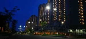
- Urban Road Lighting Upgrade in Indonesia
In an urban road lighting project in Indonesia, SRESKY SSL-310 solar street lights were used in conjunction with existing 10-meter light poles and solar-powered lighting systems. This project illustrates why, when upgrading urban roads, it is essential to assess the existing light pole infrastructure, installation constraints, and power supply options before finalizing the lighting design;
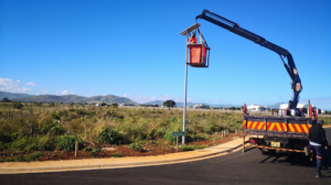
Mauritius Coastal Highway Lighting Design
The Mauritius Coastal Highway project deployed 260 Atlas Series solar street lights, which can serve as a reference for coastal road lighting applications. For similar projects, corrosion resistance, wind resistance, and protection requirements must still be verified based on specific product specifications, structural calculations, and on-site conditions.
VIII. How Should the Life-Cycle Cost of a Solar Street Lighting Project Be Evaluated?
For government procurement, EPC projects, and commercial infrastructure developments, the initial purchase price does not fully reflect the system’s total cost.
Life-cycle cost (LCC) typically includes equipment procurement, transportation, foundation construction, installation and commissioning, battery replacement, equipment maintenance, fault repairs, and—when evaluating conventional grid-connected alternatives—electricity bills and power supply infrastructure costs.
For remote roads where grid connection is difficult, solar streetlights may reduce costs associated with cable laying, road excavation, and power infrastructure construction. However, if a project already has a stable, low-cost power supply or requires exceptionally high power supply continuity, standalone solar, hybrid solar-grid, and conventional grid-connected lighting solutions should be compared.
For a meaningful comparison, use a consistent analysis period, discount rate, equipment replacement cycle, and maintenance assumptions. Reliability, maintenance complexity, and failure risks should also be included in the evaluation.
Solar streetlights are not necessarily the most economical option for every project. Only a comprehensive analysis of site conditions and full life-cycle costs can determine the most suitable solution.
IX. How Are Solar Road Lighting Projects Constructed and Accepted?
Before construction begins, verify the lighting design drawings, pole locations, foundation dimensions, underground utility lines, PV module orientation, and equipment compatibility. Complete all necessary structural and wind-load verifications.
After installation, inspect electrical connections, grounding, surge protection, waterproofing, controller settings, battery protection functions, and luminaire aiming.
Project acceptance should include inspections and tests based on applicable standards and contractual requirements, covering:
- Average luminance or illuminance and the relevant uniformity metrics.
- Luminaire light distribution, glare control, and lighting performance in critical areas.
- Battery charging and discharging, low-battery protection, and dimming functions.
- Remote monitoring, fault alerts, and communication functions, where applicable.
- Required continuous-operation tests and verification of the energy system.
At handover, prepare an equipment inventory, warranty documentation, spare parts plan, and maintenance procedures to support long-term operation.
X. Solar Street Lighting Project Design Checklist
Before finalizing the design, confirm that the following requirements have been addressed:
- Road classification, applicable lighting standards, and target performance metrics have been clearly defined.
- Surveys of road cross-sections, traffic conditions, and the site environment have been completed.
- Monthly solar resource data has been obtained.
- Operating hours, dimming strategies, and autonomous operating requirements have been established.
- Lighting simulations have been completed using actual luminaire photometric data.
- Energy consumption and capacity calculations for the PV modules, batteries, and overall system have been completed.
- The energy balance for the least favorable month has been verified.
- Structural safety, corrosion protection, and electrical protection have been evaluated.
- Maintenance and spare parts supply plans have been developed.
- Life-cycle costs have been compared.
- Installation, commissioning, and final acceptance requirements have been clarified.
Frequently Asked Questions (FAQ)
1. Are Solar Streetlights Suitable for Highways?
Suitability depends on road lighting standards, local solar resources, power supply reliability, and maintenance conditions. Solar streetlights may be suitable for critical areas of certain highways or sections where grid connection is difficult. However, each proposed solution must be validated through lighting simulations and energy calculations rather than assumed to be suitable for all highways.
2. What Battery and PV Module Capacities Are Required for Solar Streetlights?
Required capacities depend on the luminaire’s actual power consumption, daily operating hours, dimming strategy, solar radiation during the least favorable month, required autonomous operating days, and system losses.
Daily energy consumption should be calculated first, followed by preliminary estimates of battery and PV module capacity. The final configuration must then be verified against actual equipment specifications and local climatic conditions.
3. Are Solar Streetlights Always More Cost-Effective Than Traditional Grid-Connected Streetlights?
Not necessarily. Solar streetlights may reduce expenses associated with cable installation, road excavation, and grid expansion. However, equipment procurement, battery replacement, and maintenance costs must also be considered.
A comprehensive comparison of the life-cycle costs of standalone solar, grid-connected, and hybrid power supply solutions should be conducted over a consistent analysis period.
Conclusion: Designing Reliable Solar Lighting Systems Based on Road Requirements
Solar lighting systems for highways, urban roads, and remote roads must balance lighting performance, energy supply, structural safety, equipment reliability, and total life-cycle costs.
A well-established design process should include road surveys, the selection of applicable lighting standards, photometric simulations, system capacity calculations, structural and environmental verification, cost assessments, and installation, commissioning, and acceptance testing.
Project case studies from Sresky can provide useful references for evaluating solutions across different application scenarios. However, the final system configuration must be determined independently based on local lighting regulations, solar resources, site conditions, and actual equipment specifications.
For government procurement agencies, EPC contractors, street lighting integrators, and commercial project developers, a truly effective solar street lighting system must do more than illuminate roads. It must deliver compliant lighting performance, a reliable energy supply, and manageable maintenance costs throughout its intended service life.