
In rural areas of many countries, roads have been built, yet they remain pitch-black at night. Connecting to the grid requires laying power lines, expanding distribution capacity, and paying electricity bills over the long term—all of which impose significant costs and O&M pressures on scattered, remote roads. Off-grid solar street lights, which do not rely on the grid, are a more practical choice.
This article explains the process step by step: when to use an off-grid solution, what to confirm before selecting a model, how to calculate the system configuration, what technical requirements to include in procurement documents, and how to evaluate the total cost of ownership.
I. When Is Off-Grid Solar Lighting Appropriate?
Solar street lights are not necessarily superior to grid-connected lights in all scenarios. The key factors in making this determination are the distance to the power grid, the degree of road dispersion, and the capacity for long-term operation and maintenance.
| Comparison Item | Grid-Connected Street Lights | Off-Grid Solar Street Lights |
|---|---|---|
| Power Supply Method | Depends on the power grid | Independent power generation and energy storage |
| Initial Construction | Cables, power distribution, and transformers | Foundation and light pole installation |
| Ongoing Costs | Electricity bills and line maintenance | No electricity bills; battery replacement and cleaning required |
| Impact of Power Outages | Affected by grid failures | Not affected |
| Suitable Scenarios | Roads near the grid, with heavy traffic and high illuminance requirements | Roads far from the grid, with scattered locations and low to moderate traffic volumes |
Off-grid solutions are typically more advantageous when roads are far from the grid, require extensive line extensions, or have an unstable grid power supply. Conversely, if a road is adjacent to existing power lines and has heavy traffic and high illuminance requirements, grid-connected power may be more suitable. Cost analyses should be conducted for both solutions, as discussed in Section VI.
II. Six Conditions That Must Be Confirmed Before Selection
Key Conclusion: Before selecting a solution, the following six conditions must be confirmed: ① road type and lighting standards; ② solar irradiance and shading during the most unfavorable month; ③ nightly lighting duration and dimming strategy; ④ climate and extreme weather conditions; ⑤ construction accessibility; and ⑥ operation and maintenance (O&M) conditions. Among these, solar irradiance, shading, and O&M conditions are the most easily overlooked, yet they most directly determine whether the system can operate reliably over the long term.
Do not ask directly, “How many watts are needed for a road?” Instead, gather the following information first.
1. Road Type, Width, and Lighting Standards
Distinguish between village roads, connecting roads, mountain roads, and arterial roads, and clarify the applicable lighting standards (e.g., EN 13201, CIE 115, or national standards). When road drawings are available, use IES photometric files to simulate the lighting in software such as DIALux, and use the results to determine pole height, spacing, and luminous flux.
2. Solar Irradiance and Shading
Design should be based on solar irradiance data for the most unfavorable month rather than annual averages. Public data sources such as the Global Solar Atlas, NASA POWER, and PVGIS can be consulted, with adjustments made to account for shading from tree canopies, mountains, and buildings.
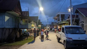
The village of Sukamaju in West Java, Indonesia, serves as a typical example. With a long rainy season, heavy shading from tree canopies, and high humidity, conventional solar street lights installed there failed during the very first rainy season. By the end of 2025, the village had deployed 450 integrated solar street lights (Sresky Atlas SSL-36M), covering approximately 21 kilometers of main village roads and public hubs and thereby achieving stable off-grid lighting. In such locations, shading losses and prolonged periods of low sunlight during the rainy season must be factored into the calculations before considering luminaire parameters.
3. Nightly Lighting Duration and Dimming Strategies
Determine the number of hours of lighting required each night, whether time-of-use dimming or PIR motion sensing is permitted, and whether higher brightness is needed at locations such as intersections, bridges, and marketplaces. These factors directly determine daily power consumption and dictate the sizing of batteries and solar panels.
4. Climate and Extreme Weather
High temperatures, prolonged rainy seasons, dust storms, salt fog, low temperatures, and strong winds can all affect battery life, luminaire protection, and pole structure. The impact of high temperatures on battery life is particularly significant, requiring attention to battery temperature protection and heat-dissipation design.
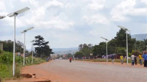
The rural road and agricultural market lighting project in the Misungwi District of the Mwanza Region, Tanzania, was completed under these constraints: insufficient local grid coverage, high installation costs for grid-connected solutions, and difficulties in ensuring long-term operation and maintenance in remote locations. The project ultimately deployed approximately 230 all-in-one solar street lights from the Sresky Atlas series, equipped with LiFePO4 batteries and temperature protection to mitigate battery degradation under high-temperature conditions. The lamp bodies are constructed from corrosion- and weather-resistant metal materials and feature a sealed structure to withstand high humidity, salt fog, and heavy rainfall. For road sections where maintenance personnel cannot access the site frequently, the value of this design lies in reducing early failures rather than merely improving performance specifications.
5. Construction Accessibility
Transportation routes, foundation conditions, the ability to bring in hoisting equipment, and the presence of overhead power lines or trees on-site all affect pole height selection and construction costs and may also limit the effective sunlight exposure of the solar panels.
6. O&M Conditions
Are there local maintenance personnel? How are spare parts obtained? How long does it take for personnel to arrive on-site after a failure? Who is responsible for battery replacement, and where does the budget come from?
In remote projects, this factor often determines the system’s condition five years down the line. It is precisely for this reason that the Misungwi project treated limited maintenance resources as a design premise.
III. How to Calculate System Configuration: Electricity Consumption, Batteries, and Solar Panels
Three Core Formulas
Daily Electricity Consumption (Wh) = Σ (Power per Time Slot × Duration)
Battery Capacity (Wh) = Daily Electricity Consumption × Number of Consecutive Rainy Days ÷ Depth of Discharge, with additional consideration given to temperature, degradation, and safety margins.
PV Panel Power (W) = Daily Electricity Consumption ÷ Effective Sunshine Hours ÷ System Overall Efficiency
Working Example: A Single 60 W Light with Two Operating Modes
Assumptions: 12 hours of nighttime lighting; 4 hours of effective sunlight in the most unfavorable month; 3 consecutive days of rain; a LiFePO4 battery with an 80% depth of discharge; and overall system efficiency of 70% (including losses from wiring, the controller, dust accumulation, and high temperatures).
Scenario A: Full-Power Operation Throughout the Night
Daily power consumption: 60 W × 12 h = 720 Wh
Battery capacity: 720 × 3 ÷ 0.8 = 2,700 Wh
Solar panel power: 720 ÷ 4 ÷ 0.7 ≈ 257 W
Scenario B: Time-of-Use Dimming
First 4 hours at 100%: 60 W × 4 h = 240 Wh
Middle 5 hours at 50%: 30 W × 5 h = 150 Wh
Last 3 hours at 30%: 18 W × 3 h = 54 Wh
Daily power consumption: approximately 444 Wh, about 38% lower than in Scenario A
Battery capacity: 444 × 3 ÷ 0.8 ≈ 1,665 Wh; with an additional 15% margin, approximately 1,900 Wh
Solar panel power: 444 ÷ 4 ÷ 0.7 ≈ 159 W; 160–180 W is recommended
| Specification | Scenario A (Full Power) | Scenario B (Dimming) |
|---|---|---|
| Daily Power Consumption | 720 Wh | approx. 444 Wh |
| Battery Capacity | approx. 2,700 Wh | approx. 1,900 Wh |
| Solar Panel Power | approx. 257 W | approx. 160–180 W |
The dimming curve must be specified during the bidding phase and serve as a uniform benchmark for both quotations and acceptance. Otherwise, quotations from different suppliers cannot be compared side by side.
Dimming is only applicable to roads with regular nighttime traffic where reduced brightness is permissible; sufficient illuminance must still be maintained at critical locations such as intersections.
Such dimming curves are typically achieved through PIR (passive infrared) motion detection and ALS (ambient light sensing) adaptive control. The system maintains a baseline brightness when no people or vehicles are present and automatically increases brightness when they pass by. During prolonged periods of overcast or rainy weather that cause battery levels to drop, the system automatically reduces output to extend lighting duration. Sresky’s smart control solution supports both of these functions, which is also a prerequisite for reducing the size of the battery and solar panels in Scenario B described above.
The formulas provide theoretical values. Actual projects must also consider battery performance at low temperatures, capacity degradation toward the end of the battery’s lifespan, dust accumulation on the panels, and the time required to fully recharge after a period of continuous rain. If recovery is slow toward the end of the rainy season, the system will repeatedly reduce brightness. Therefore, the design should allow for additional capacity in the solar panels or batteries.
IV. Reference Configurations for Common Road Types
The table below assumes time-of-use dimming, a 3-day battery reserve under overcast or rainy conditions, and approximately 4 hours of effective sunlight. These figures are for preliminary estimation only; final parameters should be recalculated according to Section III and based on DIALux simulation results.
| Road Type | Width | LED Power | Battery Capacity | Solar Panel | Light Pole Height |
|---|---|---|---|---|---|
| Village Roads | 3–5 meters | 30–40 W | 300–500 Wh | 50–100 W | 5 meters |
| Rural Connecting Roads | 5–8 meters | 50–80 W | 500–1,000 Wh | 100–200 W | 6–8 meters |
| Mountain Roads | 4–6 meters | 60–100 W | 800–1,500 Wh | 150–250 W | 8 meters |
| Remote Arterial Roads | 8 meters or more | 100 W or more | 1,500 Wh or more | 250 W or more | 8–10 meters |
Estimated Lamp Spacing: Generally 3–5 times the installation height. For a 1-kilometer road with 6-meter lamp posts, single-side installation, and a spacing of 30 meters, approximately 34 sets are required, including both ends. Thirty meters is close to the upper limit for spacing with 6-meter posts. The number of units will increase accordingly when there are many curves, the road is wider, or the lamps are installed on both sides.
V. Integrated or Split-Type?
| Comparison Criteria | Integrated | Split-Type |
|---|---|---|
| Structure | PV panel, battery, and luminaire integrated into the lamp head | PV panel, battery box, and luminaire installed separately |
| Installation | Simple; quick transportation and installation | Requires wiring and securing the battery box |
| Maximum Capacity | Limited by lamp head size and weight; commonly used for small- to medium-power applications | Can be equipped with high-capacity batteries and large-area PV panels |
| Shade Management | Panels and lamp head are in the same position, leaving little room for adjustment | Solar panels can be individually oriented or mounted higher |
| Battery Maintenance | Replacement requires working at heights | Battery box allows for easy inspection and replacement |
| Theft Protection | Components are concentrated at a high elevation, making theft difficult | Ground-level battery boxes require anti-theft design |
| Typical Scenarios | Village roads and connecting roads with limited construction conditions | Mountainous areas, sections with heavy shading, and routes requiring high-capacity energy storage |
When capacity requirements are low and shading is not severe, the integrated design reduces installation costs. When the required battery capacity or photovoltaic panel area exceeds the load-bearing capacity of an integrated design, or when photovoltaic panels need to be installed in unobstructed locations, the split-type design is more suitable.
For village road and market projects such as Sukamaju and Misungwi, which require rapid, large-scale installation, selecting an integrated design can significantly reduce installation complexity.
VI. Procurement Technical Specifications and Life-Cycle Cost
Key Conclusions: The bidding documents should clearly specify the battery type and cycle-life test conditions, controller and dimming functions, protection rating (luminaires must be at least IP65), and warranty and certification requirements for each component.
Costs should be calculated based on a 10–15-year full life cycle:
Total Cost = Equipment and Installation + Battery Replacement + Inspection, Cleaning, and Maintenance + Replacement Due to Damage or Theft
It is more prudent to budget for battery replacement based on a 5–8-year replacement cycle.
Recommended Content for Tender Documents
| Item | Recommended Focus Areas |
|---|---|
| Battery | Prioritize LiFePO₄; require specification of cycle-life test conditions (temperature and depth of discharge), and provide transportation safety certificates such as UN38.3 |
| Battery Protection | Overcharge, over-discharge, overcurrent, and short-circuit protection; high- and low-temperature charging protection |
| Controller | MPPT priority; supports multi-level dimming and PIR sensing; automatic power reduction when battery levels are low |
| Solar Panels | Rated power, conversion efficiency, and performance degradation warranty |
| Light Fixtures | Luminous efficacy (lm/W), IES light distribution files, color temperature, and anti-glare design |
| Protection Rating | Light fixtures must be at least IP65; consider IP66 for coastal or rainy regions; impact resistance should be IK08 or higher |
| Corrosion Resistance | Materials and surface treatments for the light body and pole; salt-spray test data required for coastal regions |
| Light Poles | Wind-resistance rating must match local wind speeds; foundation design drawings must be provided |
| Warranty | Specify the warranty period and replacement responsibilities separately for luminaires, batteries, solar panels, and controllers |
| Certifications | Such as ISO 9001, CE, RoHS, etc.; verify the validity of certificates |
| Remote Monitoring | Capable of reading battery charge levels, fault status, and dimming parameters; suitable for projects where frequent on-site inspections are difficult |
Total Life-Cycle Cost
Focusing solely on the purchase price can easily lead to an underestimation of future expenses. It is recommended to calculate costs over a 10–15-year period:
Total Cost = Equipment and Installation + Battery Replacement + Inspection, Cleaning, and Maintenance + Replacement Due to Damage or Theft (if applicable)
When comparing with grid-connected solutions, also factor in the costs of extending power lines, installing transformers, paying long-term electricity bills, maintaining power lines, and obtaining grid connection approval.
Several variables need to be estimated in advance:
Battery replacement cycle: The actual lifespan of LiFePO₄ batteries is significantly affected by temperature and depth of discharge; it is safer to budget for a 5–8-year replacement cycle.
Maintenance response costs: In locations with poor transportation access, the cost of a single on-site repair may exceed the cost of the part itself.
Risk of failure: If street lights fail en masse during the first rainy season, this will result in replacement expenses and a loss of public trust—a risk that is most often overlooked in low-cost solutions.
VII. Five Common Selection Mistakes
1. Comparing Only Prices
Low prices often result from using smaller batteries and solar panels or lowering the protection rating, leading to higher replacement costs later on.
2. Focusing Solely on LED Power
A 100 W LED is not necessarily better than a 60 W one. Light distribution, pole height, spacing, and luminous efficacy collectively determine road-surface illuminance.
3. Designing Based on Average Annual Sunshine Hours
The most unfavorable month should be used as the basis, and shading should be factored in.
4. Failing to Specify Dimming Curves and Acceptance Criteria
Since suppliers use different benchmarks in their quotations, it is difficult to determine during acceptance testing whether the system meets the required standards.
5. Neglecting O&M Arrangements
Without plans for cleaning, inspections, and battery replacement, even the most reliable system will gradually degrade.
In remote areas, dust and bird droppings can continuously obscure solar panels, reducing charging efficiency, while the cost of on-site manual cleaning is high. To address this, products with automatic cleaning features can be selected, such as the Sresky Thermos series, which can automatically clean solar panels up to four times a day. According to manufacturer data, this can increase charging efficiency by more than 20% and maintain stable power generation even under unattended conditions.
VIII. Frequently Asked Questions (FAQ)
How many solar street lights should be installed along a rural road?
This depends on the road length, pole height, road width, and illuminance requirements. The spacing is generally 3–5 times the installation height. For example, for a 1-kilometer road with 6-meter poles, single-side installation, and 30-meter spacing, approximately 34 sets would be required. The specific number should be determined based on IES files and DIALux simulations.
Can solar street lights be installed on roads with severe tree shading?
Yes, but this must be addressed during the design phase. Select locations with minimal shading; prune branches and foliage; appropriately increase pole height, PV panel power, and battery capacity; and implement adaptive dimming to automatically reduce power output when battery levels are low, thereby preventing premature shutdown.
If necessary, consider a split-type design and install the PV panels in an unobstructed location.
How can long-term maintenance costs be reduced?
Select long-life batteries and corrosion-resistant, waterproof lamp housings; establish a cleaning schedule for areas with high levels of dust or bird droppings, or evaluate the actual benefits of automated cleaning solutions; utilize remote monitoring and adaptive dimming; and build sufficient design margins into the system to prevent it from operating at its limits over the long term.
Conclusion: The Key to Selecting Solar Street Lights for Rural Areas Is Long-Term, Reliable Operation
The key to the success of a rural road solar lighting project is not choosing the highest-wattage lights, nor is it selecting the lowest-priced products. What truly matters is:
- Designing according to road requirements;
- Performing calculations based on local solar resources;
- Selecting a reliable energy storage system;
- Considering long-term maintenance costs.
For remote areas, solar street lights are not merely lighting fixtures; they are green energy solutions that support the development of rural infrastructure. Only through accurate calculations, reasonable configuration, reliable products, and long-term service can solar street lights truly realize their value, providing continuous, safe, and sustainable nighttime lighting to more regions without a stable power grid.